Home Assignments About Final Project

Rodrigo Shiordia

Week 15 Assignment: Molding and Casting


Designing a Parametric Part in Fusion Planning Toolpaths in Fusion Milling the mold Casting the parts Assignment Files Group Assignment

Plunger Design with parametric sketching in Fusion 360

The dseign of a rubber plunger head

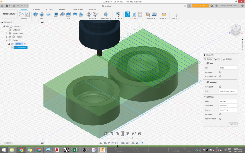
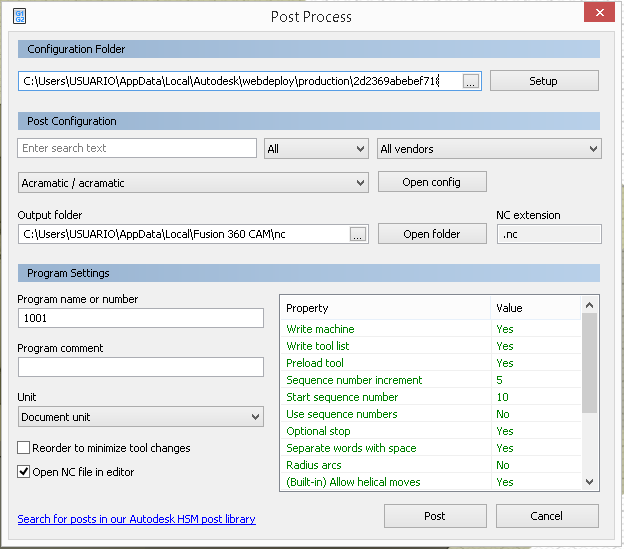
A part of my final project would be benefitial to have made of elastomeric material. Namely Sillicone rubber would be great for the plunger design that I'm planning. Refer to the Final project tracking page for more information. This part will be inside an acrylic tube and will be attached to a stiff plunger. I am still in the process of choosing an appropiate acrylic tube, so the plunger design necessarily needs to be parametric. I could have done it in grasshopper, however, since I don't have lab access, the toolpath planning needs to be done in an available sotware. In the lab, we use Rhino CAM, but we don-t have access to that here at home. I downloaded a trial version of Fusion 360. Autodesk is offering commercial access to it, but my autodesk id is old and I had already downloaded Fusion, so I couldn-t use the full version. That means saving was not an option.
Fusion is a very powerful tool for product design and has a number of workbenches. I am new to fusion or these kinds of softwares, so I kept it simple. I modelled two parts, a rigid plastic cap for the tube and a flexible sillicone rubber plunger head. It is like the ones you see inside syringes, only bigger.


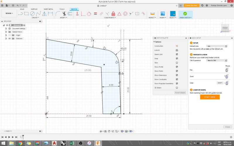
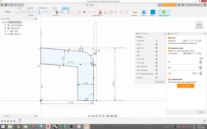
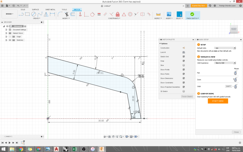
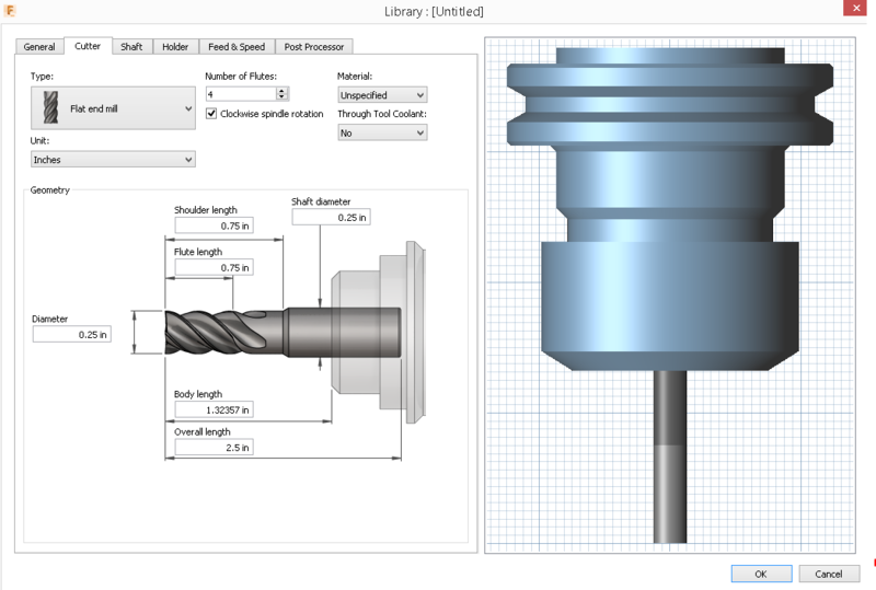
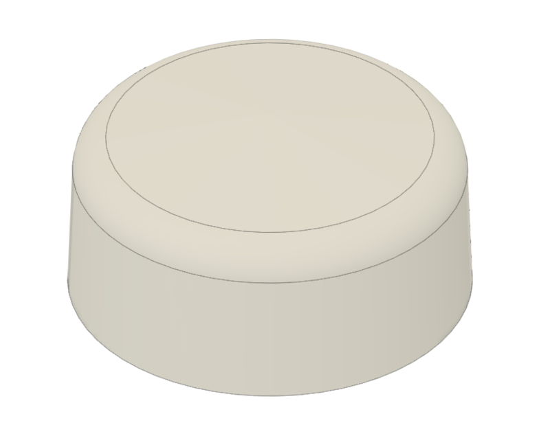
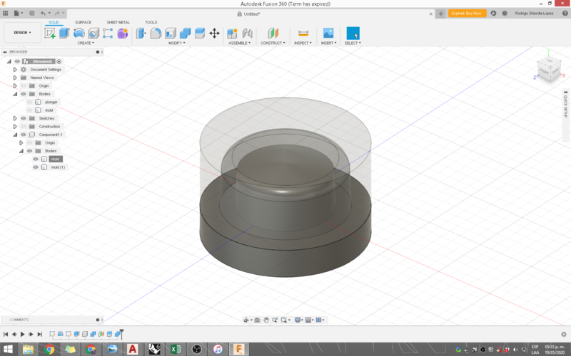
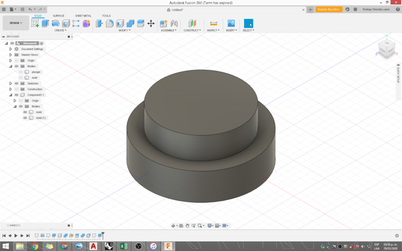
The first thing I did was to create a 2d sketch in a front view. I constrained everything so that I could control part diameter, wall thickness, draft angle. I'm using 2° draft angle as recommended on this page The above images show the different configurations that I get from varying the parameters. Fusion constrains everything as you draw it, so you need to force it to onstrain what you want. After the sketch was created I made a solid by revolving the sketch around a construction line at the center of the model. This is the modeled part:
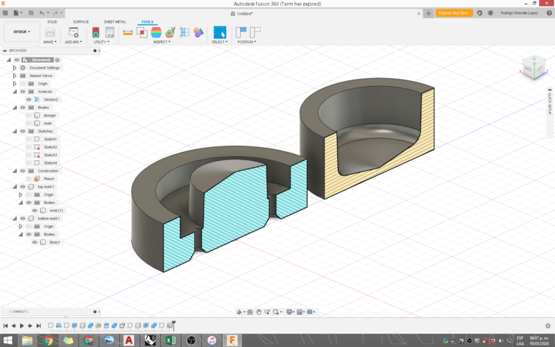
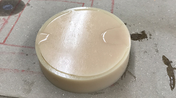
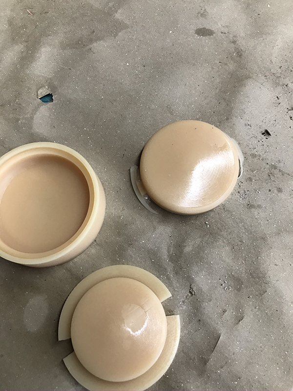


Modeling the mold

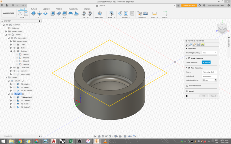
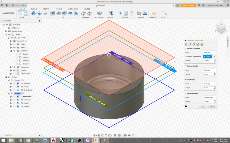
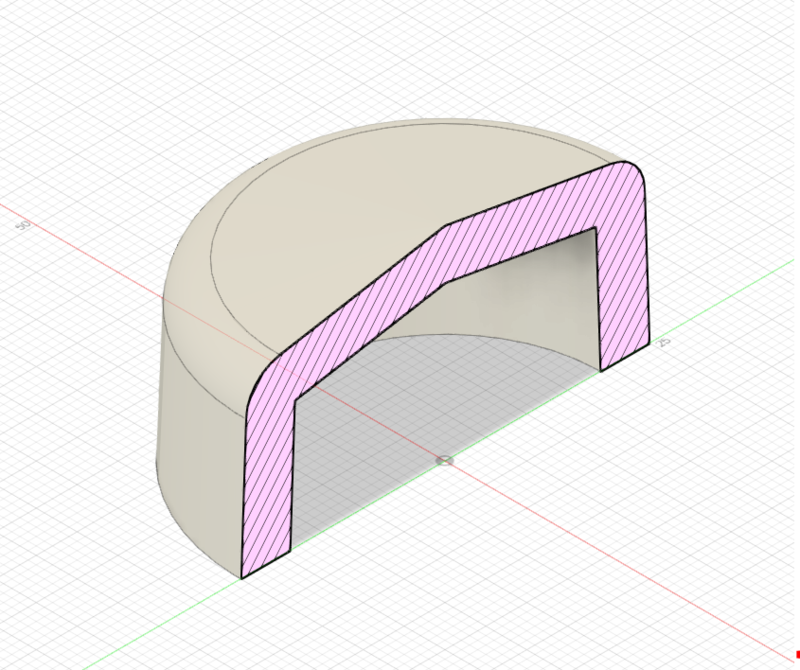
The mold needs to be a two part mold. Both inside and outside surfaces need to have a draft angle for demolding, again, I sed 2 degrees.
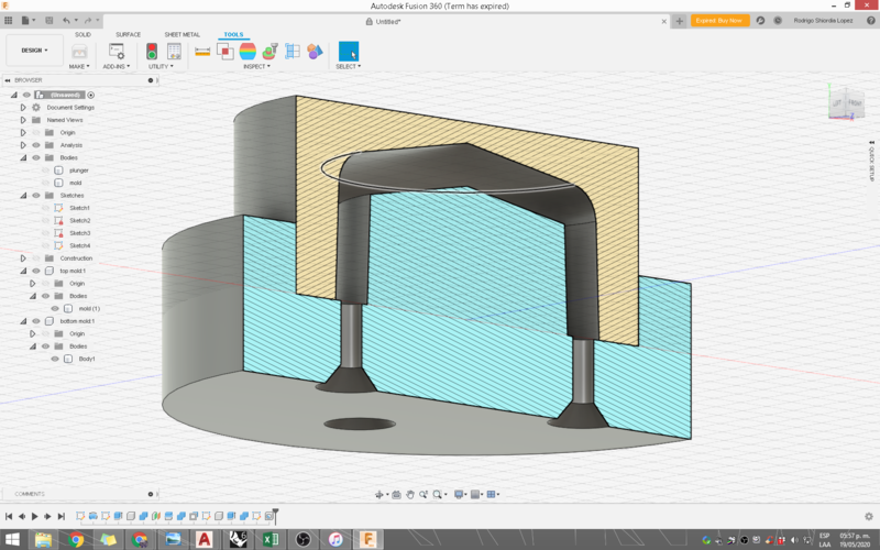
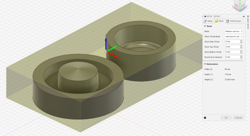
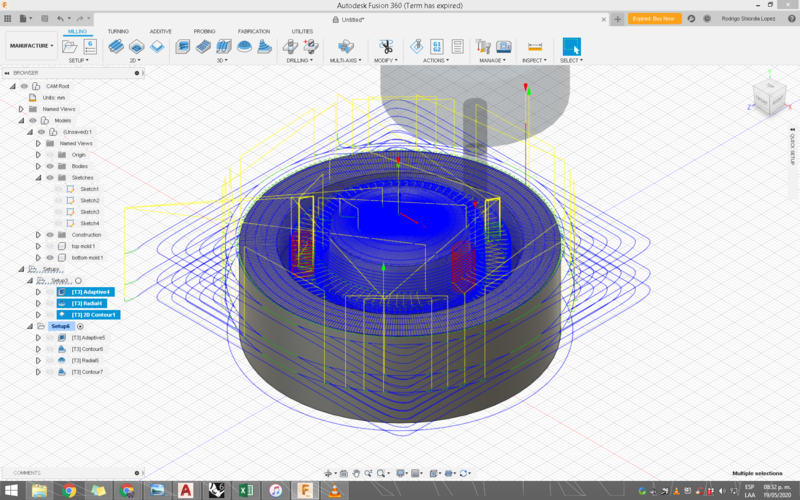
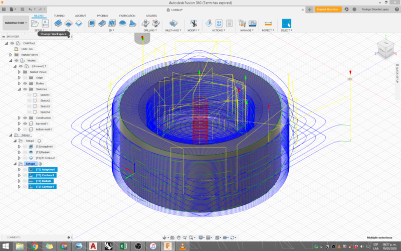
For the two part mold, I first created a cylinder that represents the assembled two part mold. I then cut the geometry from the positive part from the cylinder, creating a cavity inside it.


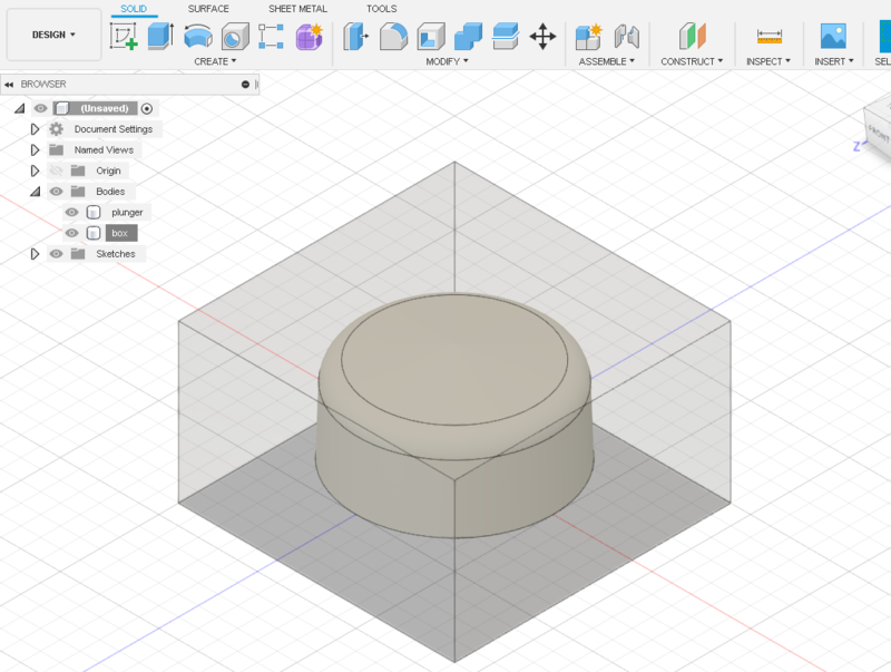
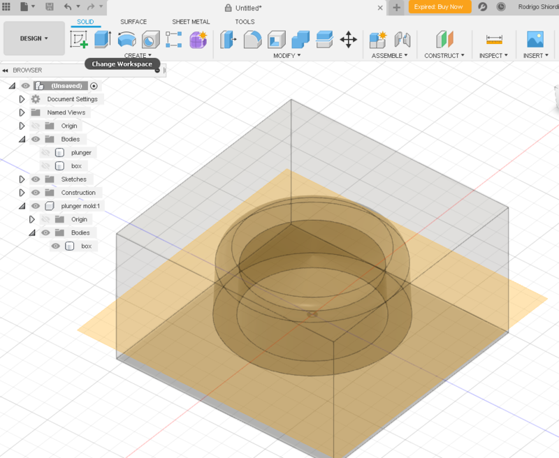
After making and cutting the box with the geometry and a construction plane, I joined the void form of the bottom of the part to the base of the mold. This was so that the mold has some floor surface and I also created a circular trim and a rim instead of creating registers. This way the whole mold is a register of itself and is constrained in every direction. Since I'm casting this part out of flexible rubber, then The mold can be the rigid milled part itself. If I wnated to make a flexible mold, I'd need to have another stage to create the mold of the mold.
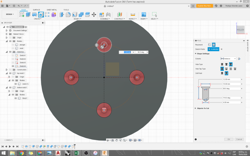
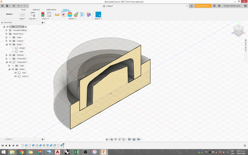
Holes for pouring

I bored four holes on the base of the mold to pur the rubber. I created a sketch to position them accrately, and sed the 'H' key in Fusion for the tool. The holes can be customized and I used countersink holes with exagerated dimensions to create funnel type surfaces for pouring.


Toolpath Planning

Setting up the stock

The first thing you need to do in Fusion to start a CAM job is to create a setup. In the setup you define the stock size, and you need to change the coordinate system because for some reason Fusion has the Z axis pointing to the front instead of UP. Most CNC machines have the Z value pointing up.


The images above show the parameters used for the setup. Milling operations ill be referenced inside the setup. To add the milling operations you need to setup a tool and select the type of operation. I started with a simple facing pass to get the feel of how to configure them. At first I also set up the mold parts side by side, but quickly decided to do one milling workflow for each of the mold parts instead of milling them both on the same job. That Way I had more control over the parameters. More importantly this allowed me to concentrate on colision avoidance with each part.


The toolpath planning has a lot of concepts that we have seen in class, this include: Milling operation, can be contour, pocket mill, adaptive clearing, radial etc. The type of operation is a function of the type of geometry that you have. I used adaptive clearing for the rough pass, and then a combination of contour and radial operations. There are also boundaries and surfaces that you can exclude.
These are the boundaries and heights I configured.

This is the tool I used, which is the one we have in the lab:

Simulating the toolpath

As I said, I started with a rough pass with adaptive clearing in 10mm increments, going fast and low tolerance and stepover. The setting is Stock to leave which is the distance between the milling operation, and the finished part. The setting for my rough pass was 1 mm.

The finishing pass was a combination of contours and radial passes the readial is the last one where the stock to leave otion is set to 0, and the tolerance is decreased to .001mm.
These are the toolpaths calculated. They are all showing at the same time which is why it is better appreciated on the screen recording of the toolpath simulation.


Exporting G Code

finally after the simulation ran wothout colision and I was happy, I could then export the gcode file. It's funny that the trial verison won't let you save, but it does let you export gcode. With this, I am ready to send the file to the machine once we get lab access.


back to top

Milling

Milling on the machinable wax

I set up the machinable wax on the machine, making sure to optimize material usage. I used the 1/8 endmill with two flutes. The mold took about 4 hours to mill because i gave it a very fine pass.


back to top

Casting

Casting Products

I bought two products, the vytaflex40 and also the PMC770 from smooth on. Both of them take about 16 hours to cure, and you have to thoroughly mix them. Vyta flex is mixed at 1 to 1 ratio, and PMC770 has two parts of A to one part of B. They are both urethane rubbers. You can see their data sheetshere and here
I chose vytaflex because it has good resistance to friction, and ease of use. And PMC770 in case I needed a more sturdy material. I cast many versions, also making small adjustments to the mold as needed to get the perfect fit for my acrylic tube. The casting process took two stages, first, cast the flexible mold, and then cast the part. remember the wax mold was the mold of the mold. The final part took two castings. spaced apart a day.


The final part is the plunger for the assembly on the clay printer.


back to top